
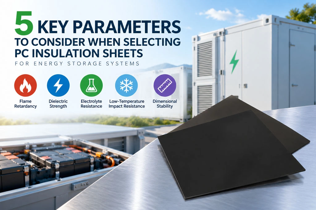
In energy storage battery packs, modules, and high-voltage electrical systems, PC insulation sheets are commonly used for cell-to-cell isolation, module side protection, busbar insulation, high-voltage component protection, and enclosure lining. Although they may appear to be simple structural components, they can directly affect the electrical safety, thermal runaway protection, and long-term reliability of the entire system.
Selecting a PC insulation sheet for energy storage applications should not be based solely on thickness and price. Five key performance parameters should be evaluated comprehensively: flame retardancy, dielectric strength, electrolyte resistance, low-temperature impact resistance, and dimensional stability.
| Key Parameter | Main Risks Addressed | Key Selection Considerations |
|---|---|---|
| Flame Retardancy | Flame propagation, secondary combustion | Flame-retardant rating, test thickness, performance after aging |
| Dielectric Strength | Electrical breakdown, creepage, short circuits | Breakdown strength, operating voltage, environmental aging |
| Electrolyte Resistance | Swelling, cracking, insulation degradation | Appearance, dimensional changes, performance retention |
| Low-Temperature Impact Resistance | Brittle cracking, edge damage | Impact toughness at minimum operating temperature |
| Dimensional Stability | Warping, shrinkage, assembly misalignment | Thermal shrinkage and differences between machine and transverse directions |
1. Flame Retardancy
Energy storage systems contain high energy densities. If a cell experiences abnormal heating or thermal runaway, an insulation material that continues to burn may accelerate flame propagation within the module or battery pack.
Therefore, PC insulation sheets should first meet the applicable flame-retardancy requirements. However, when comparing different materials, it is not enough to look only at a rating such as “V-0.” The following factors should also be confirmed:
- The test standard corresponding to the flame-retardant rating;
- The actual thickness of the tested sample;
- Whether the material color, surface treatment, and formulation are consistent with the mass-produced product;
- Whether flame-retardant performance remains stable after punching, bending, and long-term thermal aging;
- Whether clear batch records and test reports are available.
The same material may achieve different flame-retardant results at different thicknesses. During material selection, samples with thicknesses and processing conditions as close as possible to the actual application should be tested. This helps avoid directly applying test results obtained from thicker samples to thinner insulation components.
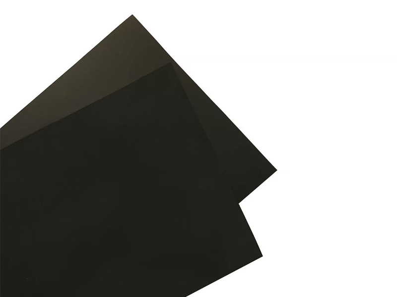
According to the published specifications of Betterial PC flame-retardant insulation sheets for energy storage applications, the product is available in thicknesses ranging from 0.05 to 1.0 mm and can achieve a V-0 flame-retardant rating, supporting different insulation structure and thickness requirements.
2. Dielectric Strength
One of the primary functions of a PC insulation sheet is to establish reliable electrical isolation between energized components. Insufficient dielectric performance may result in localized electrical breakdown, creepage, or even high-voltage short circuits.
Three aspects should be considered when evaluating dielectric performance.
The first is the material’s dielectric breakdown strength, which indicates the electric field strength that a unit thickness of material can withstand. The second is the overall voltage withstand capability at the actual application thickness. The third is the retention of electrical performance after exposure to high temperatures, high humidity, electrolyte contact, and long-term aging.
It is important to note that flat laboratory test specimens differ significantly from actual processed components. Punched edges, bends, burrs, scratches, and localized thickness variations can all become electrically weak points.
Therefore, system design should not rely solely on the theoretical breakdown strength of the material. An appropriate safety margin should also be established based on factors including:
- Rated voltage and maximum transient voltage of the energy storage system;
- Minimum actual thickness and thickness tolerance of the insulation sheet;
- High-temperature, high-humidity, and contaminated environments;
- Edge conditions after die-cutting, punching, and bending;
- Electrical clearance and creepage distance;
- Required product service life.
A reliable selection approach is to first screen materials through material-level testing and then perform voltage withstand testing on actual processed components.
3. Electrolyte Resistance
PC insulation sheets may come into contact with electrolyte due to cell leakage, residual electrolyte from filling processes, or abnormal operating conditions.
If the material has insufficient compatibility with the electrolyte, it may exhibit whitening, swelling, cracking, embrittlement, dimensional changes, or degradation of its electrical insulation performance.
These problems may not become immediately apparent during initial contact but can gradually worsen during long-term operation. Therefore, electrolyte resistance testing should not focus only on visible surface corrosion. Performance before and after electrolyte exposure should also be compared in terms of:
- Changes in mass and dimensions;
- Tensile strength and elongation at break;
- Impact performance;
- Volume resistivity or voltage withstand capability;
- Surface cracking, tackiness, discoloration, or delamination.
Test conditions should be as close as possible to the actual application environment, including the electrolyte system, immersion temperature, contact duration, and mechanical stress on the material.
If a project uses a special electrolyte formulation or specific additives, compatibility testing using the customer’s actual electrolyte is recommended.
4. Low-Temperature Impact Resistance
Outdoor energy storage systems may experience low-temperature transportation, operation in cold regions, and repeated thermal cycling.
Some materials maintain good toughness at room temperature but may become brittle as temperatures decrease. Under assembly stress, vibration, or impact, this can result in cracking or breakage.
Once an insulation sheet cracks, it may create sharp edges, expose energized components, or compromise the original creepage and insulation distances. Therefore, low-temperature impact resistance should be tested according to the project’s minimum operating temperature rather than relying solely on room-temperature data.
During validation, particular attention should be paid to:
- Whether cracks or fragmentation occur after low-temperature impact;
- Whether punched holes, notches, and bent areas fail prematurely;
- Whether toughness is retained after repeated thermal cycling;
- Whether thin-gauge materials are prone to tearing under assembly and vibration conditions;
- Whether flame-retardant modification significantly affects low-temperature toughness.
For outdoor energy storage projects in cold regions, validation should be conducted using production-equivalent samples with the actual thickness, color, and flame-retardant formulation.
5. Dimensional Stability
PC insulation sheets used in energy storage systems typically undergo die-cutting, punching, bending, or thermoforming and must precisely fit cells, busbars, and enclosure structures.
If the material experiences significant shrinkage or warping under high temperatures or repeated thermal cycling, it may cause hole misalignment, raised edges, and insufficient insulation coverage.
Dimensional stability is mainly evaluated through thermal shrinkage, thermal expansion behavior, and differences between the machine direction (MD) and transverse direction (TD).
In addition to total shrinkage, MD and TD values should be evaluated separately. Excessive differences between the two directions may increase the risk of deformation during processing and complicate material layout and component design.
Dimensional Stability of Betterial PC Insulation Sheets
- For thicknesses ≤ 0.175 mm:
MD thermal shrinkage ≤ 1.5%;
TD thermal shrinkage ≤ 0.5%. - For thicknesses > 0.175 mm:
MD thermal shrinkage ≤ 1.0%;
TD thermal shrinkage ≤ 0.5%.
Low and controllable thermal shrinkage helps maintain die-cut dimensions, hole positions, and assembly accuracy. This is particularly important for energy storage insulation components with strict requirements for insulation coverage and structural tolerances.
Selecting PC Insulation Sheets for Energy Storage Systems Requires More Than a Single Parameter
A suitable PC insulation sheet for energy storage applications should achieve a balance among flame retardancy, electrical insulation, chemical stability, low-temperature toughness, and dimensional accuracy.
A material with a high flame-retardant rating but poor low-temperature toughness may still create reliability risks. Similarly, a material with high initial dielectric strength may become unsuitable if its electrical performance deteriorates significantly after electrolyte exposure. Poor dimensional stability can also compromise insulation coverage and assembly accuracy over long-term operation.
In practical material selection, it is recommended to follow a systematic validation process:
Material data verification → Actual-thickness sample evaluation → Die-cutting and bending validation → Environmental reliability testing → Complete system validation
Suppliers should also be required to provide samples and test documentation that are consistent with the specifications, formulations, and processing conditions of the final mass-produced material.